Solar Drainback System Diagram
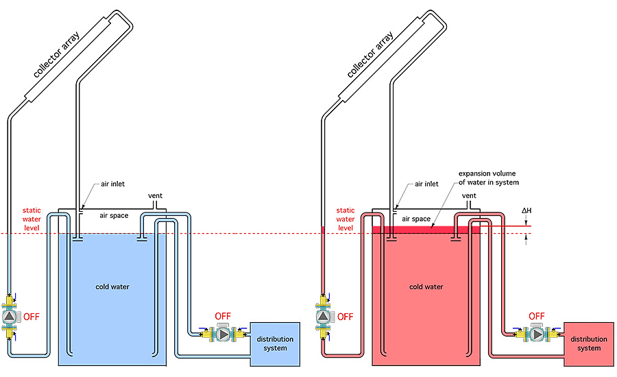
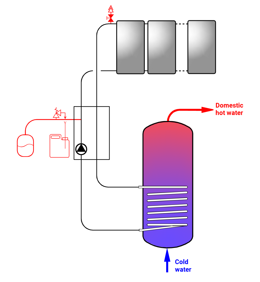
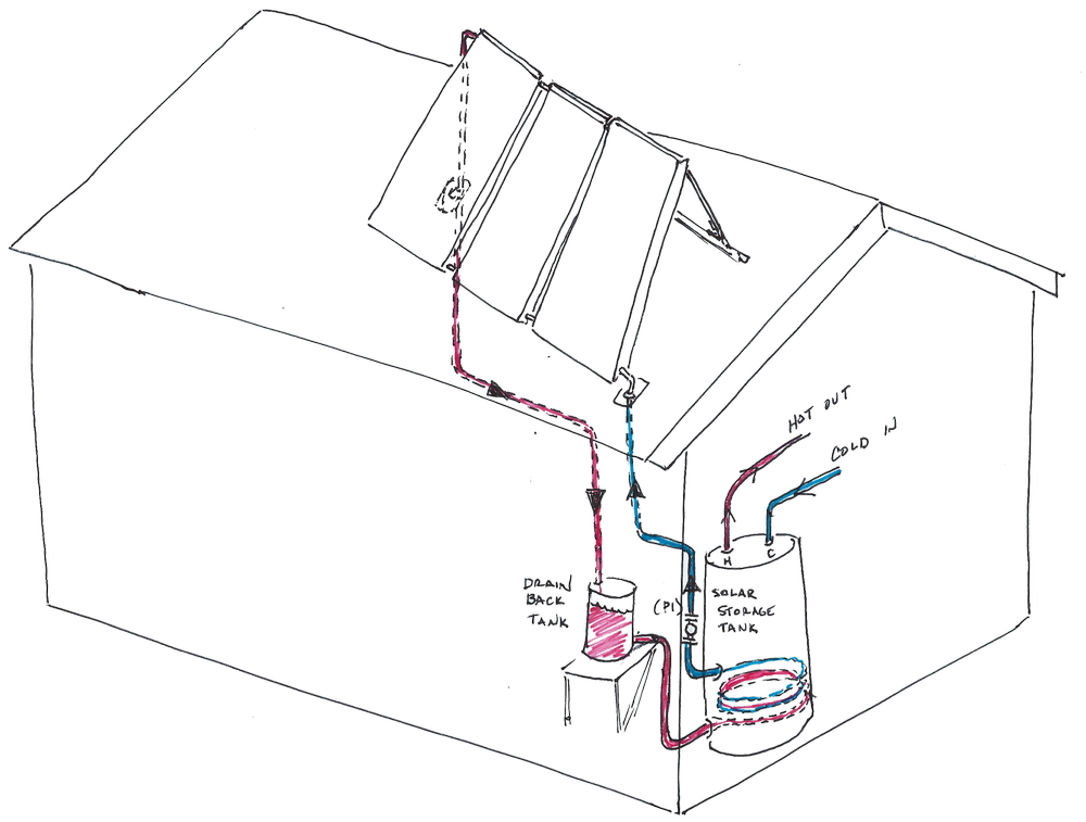
Solar drainback system diagram. Having a twin coil cylinder installed is like having a combined dedicated solar cylinder and a normal cylinder at the same time. Understanding Solar Hot Water Systems The Drain Back Design. Beyond the array use max slope to tank.
DBU with double drainback vessels Double DBU examples. 2 KiloWatts 4 KiloWatts and 8 KiloWatts. Tank 1 33 gallons of stored solar heated water.
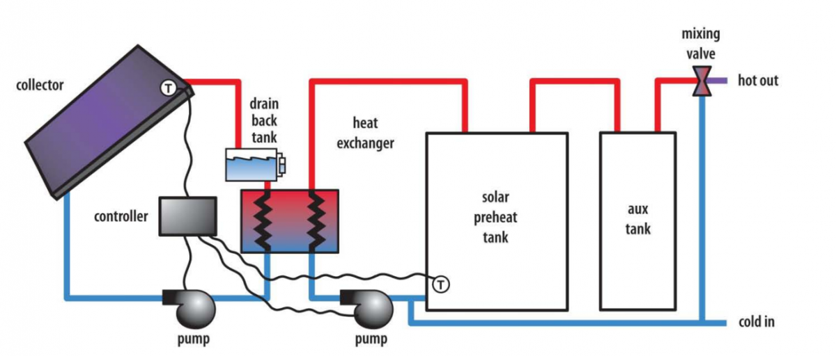
This setup works much like the submersed exchanger option in that it needs a second pump. Double Tank System with a Third Tank for Backup. Indirect solar water drainback systems are also a indirect design that use a heat exchanger to separate the collector loop from the potable water.
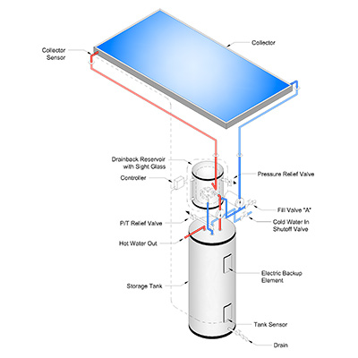
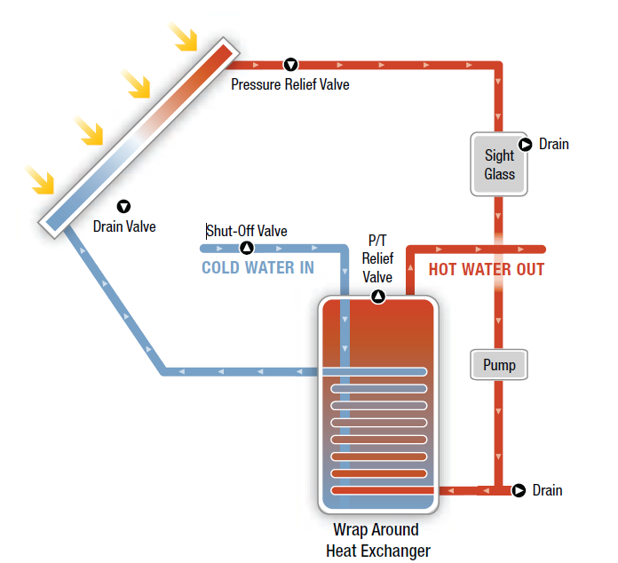
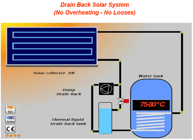
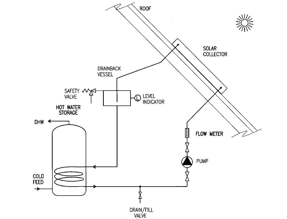
Single pass dhw drainback system design collector supply and return lines on array must slope 1 in 20 ft toward the supply. Below is a simple drain back system diagram showing the small drainback tank. These system sizes are based on 100 watt solar panels and 5 hours of average daily sunshine.
Below is a simple drain back system diagram showing the small drainback tank. DBU and pipe diagram B2 Figure 4. The Drainback has been designed to be a complete solar appliance that incorporates ease of installation and maximum efficiency for years of trouble-free service.
This does not include the additional related various subsets of components which may or may not be required depending on your installation. Drainback system diagram 8-22-12. Notice in this configuration that only one pump is required to operate the entire system for solar heat collection space heating distribution as well as domestic hot water.
In this case the same exchanger is used to transfer heat from the collectors when the system is running and from the drainback tank when the system is idle. This process begins whenever the sensors attached to the collector detect useful sunlight available which happens when the temperature in the collector is higher than the temperature of the water at the bottom of the storage tank.
Below is a simple drain back system diagram showing the small drainback tank.
A system based on drainback also called a self-draining or gravity drain system allows the solar collectors to drain naturally and passively every time the circulation pump stops. The fluid is thus immune to overheating and freezing. Having a twin coil cylinder installed is like having a combined dedicated solar cylinder and a normal cylinder at the same time. DBU with double drainback vessels Double DBU examples. Row 1 collector pump solar storage tank typical mounting for collectors parallel to sloped roof bypass valve cw inlet. Two types of technology exist. The DX Drainback system uses the suns energy to heat your water reducing your electricity consumption. DBU and pipe diagram B2 Figure 4. Solar Systems Installation Start-Up Maintenance Parts Warranty For Residential and Commercial Use DB Models 272 Duchaine Blvd.
Double Tank DHW - 2 port tank. Things like interconnecting cables solar panel mounts brackets branch Y adapters combiner boxes circuit breakers shunts and meters grounding hardware and other details. Double Tank System with a Third Tank for Backup. DHW Instantaneous Space Heat. Below is a simple drain back system diagram showing the small drainback tank. They also use a differential controller to start the pump or the pumps and to route the water into the system. Understanding Solar Hot Water Systems The Drain Back Design.













Post a Comment for "Solar Drainback System Diagram"